Metal foam supported solid oxide fuel cell
A method for the production of a mechanically robust metal foam supported solid oxide fuel cell is presented. The fuel cell allows a quick start up, exhibits increased power densities and can be run at lower temperatures.
Challenge
Within the scope of the energy revolution, fuel cells play a key role for future energy systems. Solid oxide fuel cells (SOFC) are suitable for the decentralized energy production, as they allow a flexible and highly efficient power and heat generation from renewable and conventional energy sources. The core piece of a fuel cell is the membrane electrode assembly (MEA), which consists of an anode layer, a cathode layer and an electrolyte membrane. Different thermal expansion coefficients of the used materials represent a high demand on the uniform and well-regulated heating process. This can lead to long start up times, in order to avoid severe damage of the SOFC. In addition, high operating temperatures (600 - 1000°C) can induce severe stresses on the peripheral devices (e.g. gas supplies and the cooling unit). Especially, the manufacturing process of the membrane stacks and their respective sealing resemble process- and cost-related issues, which makes SOFC sensitive and expensive.
Our solution
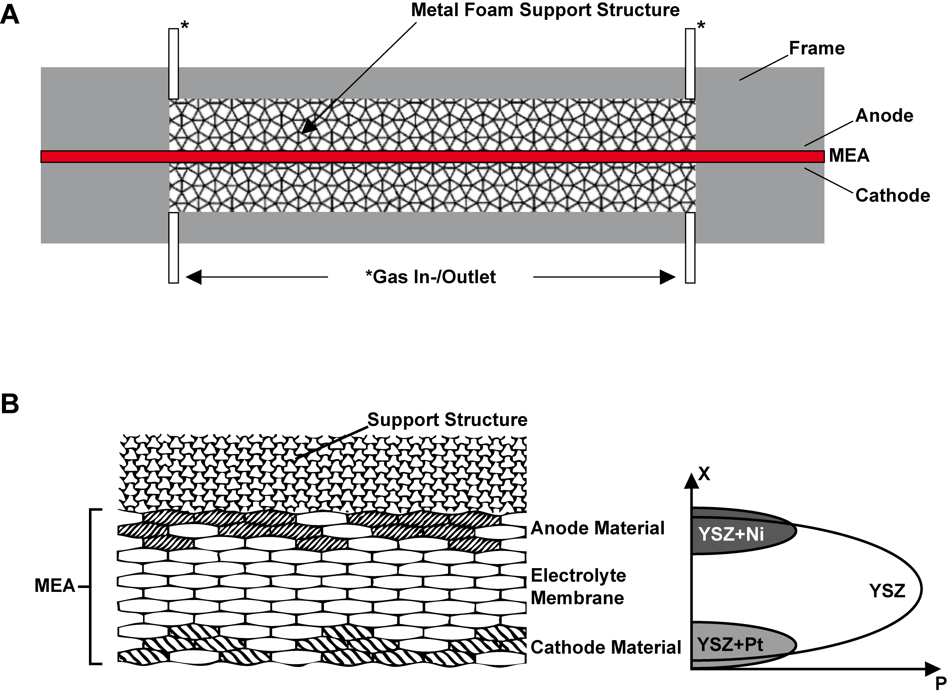
Scientists from the Clausthal University of Technology have developed a novel method for the production of a mechanically robust and energy efficient metal foam supported (MFS) SOFC, which solves the aforementioned issues. The present MFS-SOFC is based on a mechanical support structure made of an open-pore metal foam (e.g. nickel foam), onto which the MEA is directly applied via vapour deposition (Fig. 1 A). Optimization of the layer thickness can make the MEA very efficient. The three functional layers of the MEA are deposited via chemical or physical vapour deposition onto the sealed support structure. The coating process can be achieved by one continuous co-deposition process, so that fluid transitions between the layers can be realized (Fig. 1 B) and the MEA can be produced with an improved tightness. The infiltration material can easily be removed afterwards by thermal or chemical treatment. Finally, another MFS structure is added to the cathode layer. To eliminate the need for additional seals, the single cells of a fuel cell stack can be arranged according to the Janus principle.

Fig.1: Cross-sectional view of a MFS-SOFC (source: Clausthal University of Technology and adaptation after patent application EP3327848B1).
To eliminate the need for additional seals, ideally the single cells of a fuel cell stack can be arranged according to the Janus principle. To achieve this, coating of anode layers onto both sides of a support structure block is performed, so that they resemble deliminations between two neighboring cells. The resulting SOFC structure exhibits excellent mechanical and thermal stability and can thus be started quickly and resist a larger number of temperature cycles (on and off cycles). Hence, it has a better long-term durability and prolonged lifetime. By expanding the three-phase boundary at the MEA region, the electricity yield and power density is increased, resulting in a higher efficiency of the SOFC, which can be run at lower operating temperatures (600°C). Hereby, the thermal stability requirements for peripheral devices (such as gas supplies or the cooling unit) are markedly reduced, resulting in an overall reduction in system costs.
Advantages
- Excellent mechanical and thermal stability
- Quick start up and superior cycling performance (on-off cycles)
- Increased air-tightness, which results in a higher efficiency
- Increased electricity yield and power density
- Lower operating temperature (reduced stress on peripheral devices)
- Improved long-term durability and prolonged lifetime
Applications
- Energy generation in power plants
- Combined heat and power units
- Decentralized energy supply
- Power and hot water or steam production
- Large scale systems for e.g. ships are possible
- Automotive engineering
Development Status
Technology successfully developed on laboratory scale. System functionality experimentally approved.
Patent Status
European patent application granted: EP3327848B1
Patent holder: Clausthal University of Technology
Contact
Dr. Mirza Mackovic
Patent Manager Technology
E-Mail: This email address is being protected from spambots. You need JavaScript enabled to view it.
Phone: +49 (0) 551 30 724 153
Reference: MM-2261-T233
www.sciencebridge.de
